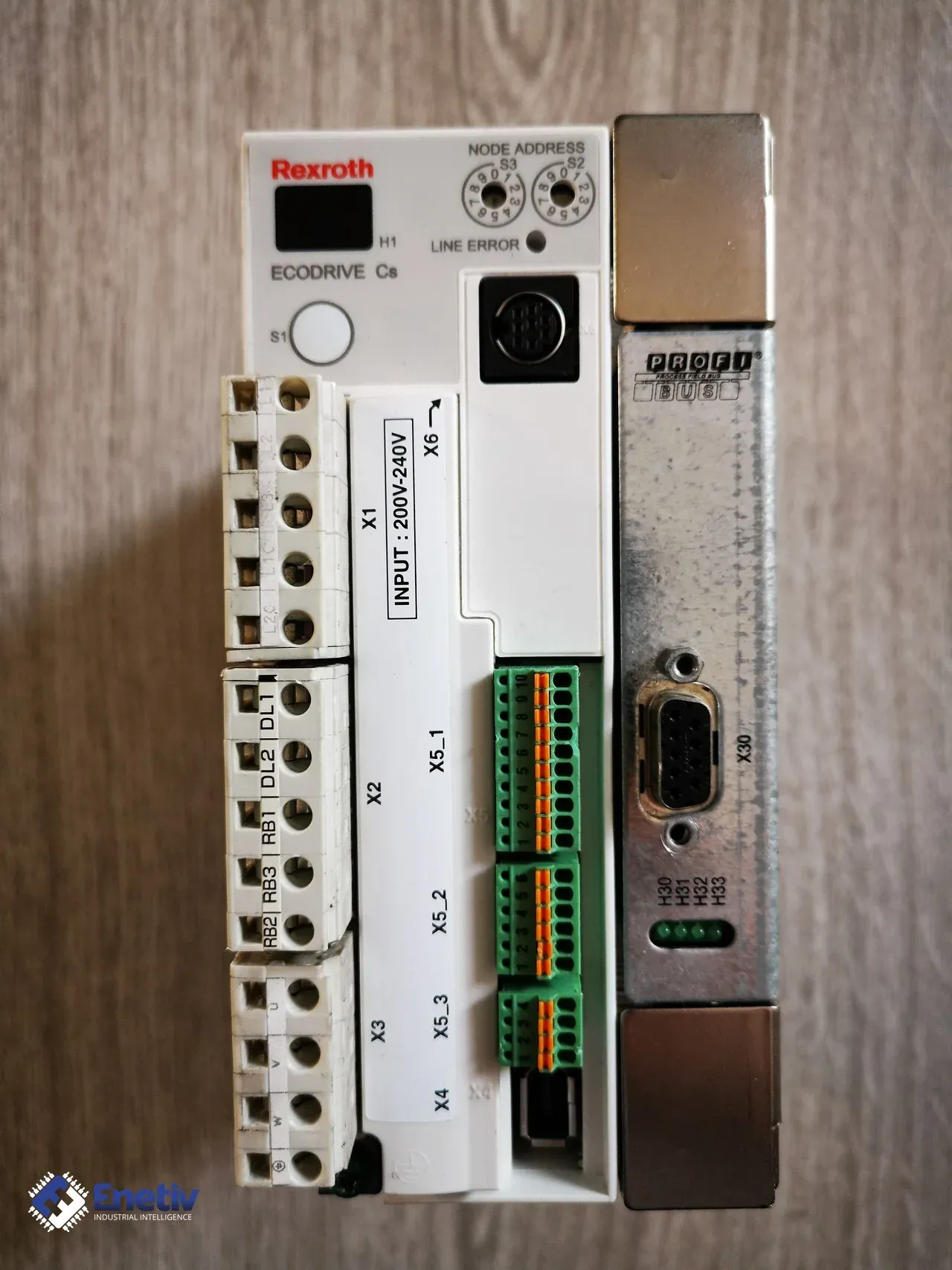
Drive on PROFIBUS-DP: node address, communication LEDs and display code - Rexroth ECODRIVE Cs, Lenze 8200 vector, Siemens MICROMASTER 4 (6SE6400-1PB00-0AA0)
Files to download
Drive not seen by the PROFIBUS-DP master? Check the node address on the DIP switches, the colour of the communication LED and fault code F0070 in MICROMASTER 4, and the EMF2133IB module in Lenze 8200 vector, before replacing any parts.
Drive on PROFIBUS-DP: node address, communication LEDs and display code - Rexroth ECODRIVE Cs, Lenze 8200 vector, Siemens MICROMASTER 4 (6SE6400-1PB00-0AA0)
A drive on a PROFIBUS-DP bus is a slave that the master in the controller addresses by its node address, so a wrong address or an interrupted connection ends with the drive stopping or not responding to setpoints. The first clue to what happened is the communication LEDs on the module and the code on the drive display. For the Siemens MICROMASTER 4 with the 6SE6400-1PB00-0AA0 module and the Lenze 8200 vector with a PROFIBUS module, setting the address and reading the communication status can be described exactly, and the same order - address, LEDs, error code, and only then replacing components - also applies to Rexroth ECODRIVE Cs servo drives with a PROFIBUS-DP card.
Siemens MICROMASTER 4 with PROFIBUS module
In the MICROMASTER 4 the node address is set on DIP switches 1-7 of the module, in the range 1-125. The switches have consecutive weights of 1, 2, 4, 8, 16, 32 and 64, and the address is the sum of the weights of the switches that are on. Address 3 is switches 1 and 2 in the on position, and address 88 is switches 4, 5 and 7 (8 + 16 + 64). This arithmetic lets you read the address "by sight" from the module and compare it with the master configuration without starting any software.
Two values have special meaning. Address 0 means the address is determined by parameter P0918, so with all switches off you have to look for the address in the drive parameters, not on the module. Addresses 126 and 127 are invalid, so a module set to either of them will not enter data exchange with the master, even though everything is physically connected.
Changing the switches does not take effect immediately. With the module already mounted, it must be done with the drive power switched off, and the new address applies only after a cold restart of the PROFIBUS module, that is, after switching the power off and on again. This applies both when the module is powered from the drive and when it is powered from a separate 24 V connection. Moving a switch "on the fly" and seeing no effect is therefore behavior in line with the design, not a fault.
The drive has only one error code for a PROFIBUS communication failure: F0070. The module has one three-color LED (green, orange, red), and its color shows which side the break is on. Orange means loss of communication with the PROFIBUS master, so the problem lies on the side of the bus, cable, connector, termination or controller. Red means loss of communication between the drive and the module, so suspicion falls on the seating of the module and on interference inside the drive.
For an orange LED, Siemens lists a weak PROFIBUS signal caused by EMC interference, cables that are too long, reflections at connections and incorrectly fitted terminals, incorrect bus termination, or impermissible stubs (T-branches). The manufacturer recommends checking the bus with an oscilloscope, and for testing PROFIBUS hardware it recommends the BT200 tester (6ES7181-0AA01-0AA0). The second group of causes is poor contact, for example a connector that is not pushed in fully or quick-connect (insulation-displacement) connector contacts not pushed all the way onto the cable, which can be found with an ordinary multimeter. For a red LED, the manufacturer points to interference entering through the analog inputs and outputs and the motor PTC/KTY input in the MM430/440, as well as a badly seated module; check that it is firmly plugged in and that the contacts on the back of the module and on the front of the drive are undamaged.
Parameter r2054 is used for diagnostics of the communication module, and it is the one to read on the panel when the LED and F0070 do not settle the matter. When commissioning the module, besides the address in P0918, the telegram failure time in P2040 is also important, as it determines how quickly the drive reports loss of communication. The module connects to the bus with a 9-pin Sub-D socket, in which pin 3 is RxD/TxD-P, pin 8 is RxD/TxD-N, and pin 6 is the 5 V ± 10 % voltage; this knowledge helps with measurement when swapped conductors are suspected.
Lenze 8200 vector with PROFIBUS module
In the Lenze 8200 vector, PROFIBUS-DP communication is provided by the EMF2133IB fieldbus module, plugged into the AIF interface. The node address is set with a DIP switch on the module, and two LEDs on the module indicate the communication status. The drive itself also has two status LEDs (red and green), which must not be confused with the module LEDs. The module works as a slave, and it detects the transmission speed in the range 9.6...12000 kbit/s by itself, so for diagnosis it does not have to be set anywhere, which removes one of the common causes of no communication.
During diagnosis it is worth noting the position of all DIP switches on the module, not just those for the address. The EMF2133IB module working with the 8200 vector supports a maximum of 3 process data words; 12 words are possible only with Servo PLC or Drive PLC. If the master is configured for more words than the drive supports, the connection will not start even though the address is correct.
The module can have an external +24 V DC ± 10 % supply, maximum 120 mA per module. The external supply is needed where the drive may be disconnected from the mains while communication with the master is to be maintained; when communication fails, check therefore that this voltage is present and within tolerance. The cable length is a maximum of 1200 m per segment, depending on speed and cable type.
What to watch for when testing
The first trap in the MICROMASTER 4 is changing the address without restarting the module: the switches are already set, yet the master still sees the old address or does not see the drive at all. That is why after every DIP change the power must be switched off and on, and only then should the LED be assessed. The second mistake is an address outside the range; 126 and 127 are invalid, and 0 refers to P0918, so a drive with all switches off may be running under an address that is not visible on the module at all.
Code F0070 is the same for different causes, so by itself it does not show whether the cable, the master or the module is at fault. Only the LED color distinguishes them: orange points to the bus and the controller, red to the connection between the drive and the module. Siemens also notes that during short communication dropouts the LED changes from green to red for 1-2 seconds, so a mere flash of color does not have to mean a permanent fault.
In addition, inspect the connector and contacts, because a quick-connect connector that is not pushed in fully can produce symptoms of interference. The bus must be terminated at both ends, and the nodes terminating the bus require a 5 V supply for the pull-up resistors; in the MM4 this is obtained by connecting a permanent 24 V supply to the module. The cable shield should be well grounded, and the bus cable should run at least 20 cm from other cables, especially power cables, and cross them at a right angle. The manufacturer stresses that an installation compliant with EMC requirements is the basis of reliable operation. The permissible segment length depends on speed: up to 187.5 kbaud 1000 m, up to 500 kbaud 400 m, up to 1.5 Mbaud 200 m, up to 12 Mbaud 100 m, and a segment may have a maximum of 32 nodes. In the MICROMASTER 4, the cables between nodes should not be shorter than 200 mm at speeds up to 1.5 Mbaud if the recommended 6GK1500-0FC00 or 6GK1500-0EA02 connectors are used.
Before changing the address, record it in the log together with the position of the other switches, and read the version markings on the housing, so that after a possible replacement the original state can be restored. With the MICROMASTER 4, remember parameter P2040: extending the telegram failure time to about 3000 ms hides short dropouts, but the drive then takes the speed setpoint from the last received telegram, which requires an assessment of machine safety.
How the check proceeds
- Read the full designation from the drive nameplate and the type of the communication module, for example 6SE6400-1PB00-0AA0 in the MICROMASTER 4 or EMF2133IB in the Lenze 8200 vector, so that the correct device description file (GSD) can be assigned in the master.
- Inspect the connector and cable: connector fully plugged in, contacts in the quick-connect connector pushed in completely, condition of the shield and bus termination at both ends.
- Read the set address from the DIP switches, in the MM4 by adding up the weights, and compare it with the master configuration; for an MM4 set to 0, read P0918.
- Observe the LEDs: in the MICROMASTER 4 orange or red, in the Lenze 8200 vector the state of both module LEDs, recorded in the log.
- Read the code on the display: in the MICROMASTER 4 F0070 and parameter r2054 as the communication module diagnostics.
- Interpretation: an orange LED with F0070 points to the bus, termination, cable length and controller; red to the seating of the module and interference inside the drive. No communication despite a correct address requires comparing the number of process data words with the capabilities of the drive, and if interference is suspected, measuring with an oscilloscope.
Before taking further action, it is worth preparing the full designation from the nameplate, the serial number, the hardware and firmware version, and photos of the nameplate, connectors and set switches. Such a set allows the module and configuration to be selected unambiguously without guessing.
Enetiv works in industrial automation from two sides: we supply parts and we repair them. We have new, used and refurbished parts from brands including Allen-Bradley (Rockwell Automation), Siemens, Schneider Electric, Bosch Rexroth and ABB, we diagnose and repair inverters, servo drives, I/O modules and controllers, and we service motors and servomotors, with our own warranty on repairs. We also specialize in end-of-life (EOL) parts and service, including older-generation and unusual components. Please contact us at https://enetiv.com/zapytanie.