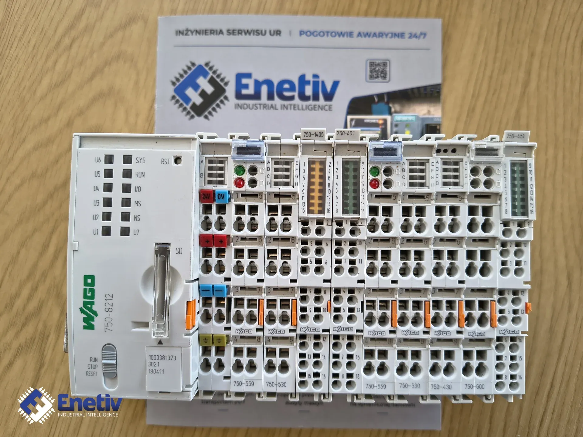
WAGO PFC200 750-8212 in the cabinet: RUN/STOP/RESET switch, LEDs, SD card and moving the program from e!COCKPIT to a replacement
Files to download
Replacing a WAGO PFC200 750-8212 controller in the cabinet: what to record before removal (switch, LEDs, SD card), how to move the program from e!COCKPIT to CODESYS 3.5, and what to watch for when choosing a replacement.
WAGO PFC200 750-8212 in the cabinet: RUN/STOP/RESET switch, LEDs, SD card and moving the program from e!COCKPIT to a replacement
The WAGO PFC200 750-8212 controller sits on the DIN rail together with 750-series input and output modules and forms the control node of a machine or installation, closed by an end module; if exactly this controller needs replacing in your cabinet, you have to make sure the program is not lost in the process. If the program was created in e!COCKPIT, which is no longer being developed, moving the project to a replacement unit requires preparation. Before the controller is disconnected, everything shown by the switch, the LEDs and the SD card must be read out of it.
Operating mode switch and reset button
According to the manufacturer's manual, the RUN and STOP positions of the switch in the 750-8212 are latching: in the RUN position the application is running, and in the STOP position all applications are stopped. The RESET position returns by itself under spring force, and depending on how long it is held it triggers a warm or cold reset, so it is not a position in which the switch can be left. Next to it is a covered reset button, pressed for example with a pen, which, depending on the switch position, temporarily sets a fixed IP address, restarts the controller or restores factory settings.
The switch position is recorded before removal, because it is part of the state in which the controller was operating, and once it is taken off the rail there is no way to reconstruct it; the record also makes it easier to set the replacement unit the same way and helps explain why the application was or was not running at all. For the same reason the switch is not moved on a running machine without agreement with the operators, because going from RUN to STOP stops all applications, and therefore also the control of a process that may still be in progress.
Users report several practical methods that they know from their own controllers. By default the controller has no IP address and looks for a DHCP server that will assign it an address dynamically. With the switch in the STOP position, holding the reset button until the RUN LED starts flashing makes the controller available at 192.168.1.17. According to these reports, a factory reset consists of holding the reset button while simultaneously moving the switch to RESET. One user also described that the SYS LED flashing orange and red meant, in his case, that a license trial period had started.
LEDs
According to the manufacturer's manual, the SYS LED shows the system state, RUN the state of the controller program, and I/O the state of the local bus, that is, the connection to the modules standing next to the controller; the MS LED relates to the module state, while NS has no function in this model, so its lack of activity means nothing. The SYS, RUN and I/O LEDs can light red, green or orange, and the meanings of the colors and flashing sequences should be taken from the manual for exactly this controller type, not guessed.
The U1…U7 LEDs are user LEDs and are controlled by the program itself through function blocks from the WAGO libraries, so their state depends on what the author of the application decided to signal, and without knowing the program they must not be interpreted as a fault. The two green LEDs A and B indicate power supply. In practice, before switching off the power it is worth taking a photo of the LEDs and the switch, because the state at the moment of failure is sometimes later the only clue for diagnosis, and it disappears permanently once the power is disconnected.
SD card
The card slot has a push-push mechanism and a sealable cover, which means that the card is pushed in until it latches and ejected by pressing it again, and the cover can be sealed if the installation documentation requires it. SD and SDHC cards up to 32 GB are supported, but all guaranteed properties apply only to a WAGO memory card, so a card from another manufacturer may work, but there is no guarantee. According to the manual the card is optional and the controller works without it, and the manufacturer provides a backup and data restore function from the card.
In practice you should check whether the card is in the slot, note its designation and make a copy of its contents before it is removed, because it is not known in advance whether it holds only a backup or also something the application depends on. Users also report that firmware can be loaded from the SD card, which makes it useful also when the controller stops responding over Ethernet.
Moving the program from e!COCKPIT to a replacement
According to the manufacturer, support for e!COCKPIT has ended and application software can be moved to CODESYS 3.5; the manufacturer also states that all e!COCKPIT functions are available in CODESYS 3.5 as well. Controllers of the PFC200 G2 series, to which the 750-8212 belongs, can therefore be programmed in CODESYS 3.5. The first step is a backup of the project from e!COCKPIT, and the second is reading the firmware version of the old controller, which is on the label on the housing and on the controller's WBM page, because it determines which environment works with it at all.
Users report that the last firmware supporting e!COCKPIT is FW22 SP1, and that from FW23 the controller works with CODESYS 3.5. This is confirmed by the manufacturer's datasheet, according to which the controller is programmed in CODESYS 3.5 from firmware release 23, and in e!COCKPIT up to release 22. One user loaded firmware intended for the 750-8202 onto a 750-8212, which ended with the loss of the MAC address and of access over Ethernet, so that the controller responded only through the service cable. The conclusion is that firmware is matched exactly to the type designation on the nameplate, not to a similar name.
What to watch out for during replacement
- Full type designation: read it from the nameplate in full, because a variant with a suffix, for example /025-000 or /040-000, is a different variant than plain 750-8212.
- Firmware and programming environment: the firmware version decides whether the program opens in e!COCKPIT or in CODESYS 3.5, so the replacement unit must have firmware compatible with the environment in which the program will continue to be maintained.
- SD card: check whether it was inserted and have a copy of its contents, because restoring data may depend on it.
- System power supply: 24 VDC with a tolerance of -25 to +30 %, and the typical current consumption is 550 mA; this value helps assess whether the existing power supply has headroom for the replacement unit.
- Interfaces: the replacement unit must have two RJ-45 sockets and a D-sub 9 socket for Modbus RTU, so that the existing network and serial cables can be connected without modifications.
- Number of modules: without bus extension the controller supports a maximum of 64 modules, which should be compared with the length of the node; in the cabinet described here the modules are 750-530, 750-430, 750-1405, 750-559, 750-451 and the end module 750-600.
- Network settings and licenses: IP addresses and licenses of additional functions must be written down beforehand, because they do not transfer by themselves and need to be checked again after the controller is changed.
From practice, it is worth adding a few checks: inspection of connectors and contacts, photos of the label and connectors, checking the LEDs after power-up, and documented origin of the controller. After commissioning, the analog channels are checked with a calibrator or a signal source, which makes it possible to detect scaling errors before they affect the process.
General replacement steps
- Make a backup of the program and configuration.
- Write down the network settings, the switch position and the LED state.
- Disconnect the power.
- Remove the controller from the rail.
- Mount the replacement unit in the same place, in front of the modules.
- Connect the power and communication.
- Start the controller.
- Load the program and licenses.
- Check the inputs and outputs and the communication.
- Document the change.
The order matters, because everything related to the old controller can be read only until the power is disconnected. That is why the settings are written down and the photos taken before removal, not after it. Finally, a description of the change, with the type designation, the firmware version and the switch position of the replacement unit, makes the next replacement easier and helps distinguish a later fault from an effect of the replacement itself.
Enetiv works in industrial automation from two sides: we supply parts and we repair them. We have new, used and refurbished parts from brands including Allen-Bradley (Rockwell Automation), Siemens, Schneider Electric, Bosch Rexroth and ABB, we diagnose and repair inverters, servo drives, I/O modules and controllers, and we service motors and servomotors, with our own warranty on repairs. We also specialize in end-of-life (EOL) parts and service, including older-generation and unusual components. Please contact us at https://enetiv.com/zapytanie.