B&R ACOPOS 1090 – Blinking RUN LED and Error 7210 (DC Bus Charging) – Complete Diagnostic Guide
Files to download
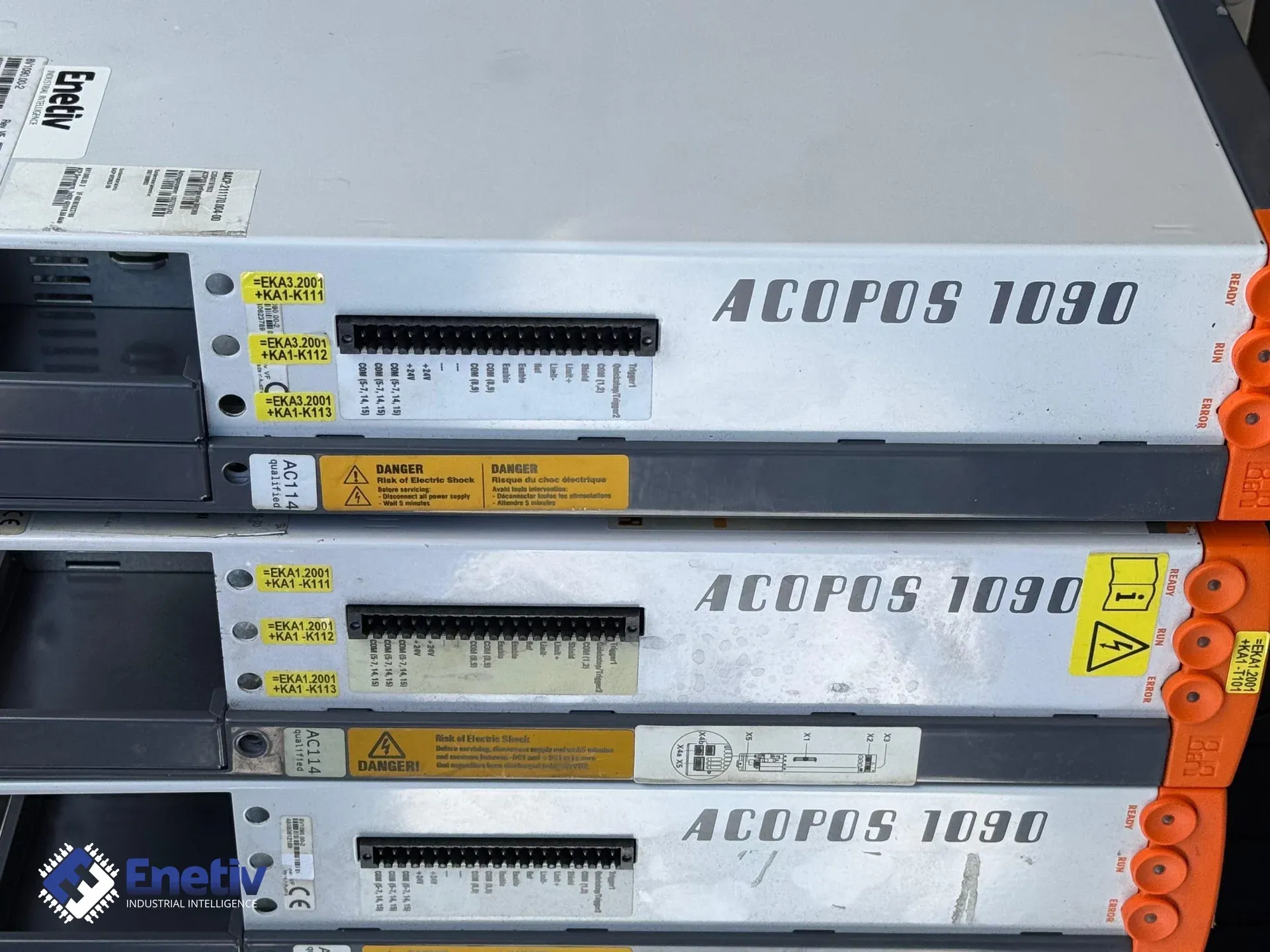
Blinking RUN LED and error 7210 in Automation Studio? A diagnostic guide for the B&R ACOPOS 1090 drive — what the DC bus: Charging: Voltage unstable code means, a step-by-step way to tell a failed RFI/EMC filter capacitor apart from an IGBT fault, and when a component-level repair makes sense versus replacing the whole drive.
B&R ACOPOS 1090 – Blinking RUN LED and Error 7210 (DC Bus Charging) – Complete Diagnostic Guide
A blinking green RUN LED and error code 7210 in Automation Studio — this guide explains exactly what that error means, how to quickly diagnose the root cause, and when a component-level repair makes more sense than replacing the whole drive.
Why do the blinking RUN LED and error 7210 appear together – what does it mean in practice?
What does error code 7210 mean in the context of DC bus charging?
Code 7210 is documented in B&R's fault list as "DC bus: Charging: Voltage unstable." This means that during the DC bus pre-charge phase, the voltage doesn't stay within the required range, which triggers an automatic output shutdown and a blinking RUN LED. Error 7210 belongs to the DC bus charging family of codes, which also includes 7200 (DC bus: Overvoltage), 7211 (DC bus: Voltage drop), 7212 (DC bus: High voltage drop), 7214 (DC bus: Charging resistor hot – too many power line fails), 7215 (Power mains: at least one phase of the power line failed), 7217–7218 (nominal voltage detection – voltage too high/too low), 7219 (DC bus: Charging: Voltage too low), 7220 (DC bus: Nominal voltage detection: Voltage not allowed), and 7221 (Mains: Failure).
What are the typical causes of unstable charging voltage?
- Damaged or aging RFI/EMC filter capacitors (noise suppression capacitors) in the charging circuit – capacitance degradation is a common, though not the only, cause of this type of fault in this class of servo drive.
- Incorrect charging cycle timing – power cycles shorter than 20 s, which can damage the charging resistor.
- Loss of one phase of the 3 × 400–480 V (±10%) mains supply to the ACOPOS 1090 (model 8V1090.00-2 or 8V1090.001-2).
- Overload of the charging resistor (error 7214) caused by repeated power cycling in short intervals.
- Incorrect supply voltage or DC bus voltage – requires checking the mains supply's correctness.
How do you check the state of the RFI/EMC filter capacitors in the ACOPOS 1090?
How does capacitor degradation affect the DC bus voltage sensors?
In the ACOPOS 1090, DC voltage is monitored by a measurement circuit connected to the noise suppression filters in the charging circuit. When these filter capacitors lose capacitance due to aging or overheating, the filter no longer smooths out noise, and the measurement transducer "sees" fluctuations as voltage dips or spikes, which can trigger error 7210 – DC bus: Charging: Voltage unstable. This is especially visible in the first few seconds of DC bus charging, when the charging resistor is under maximum load. The exact parameters (capacitance, rated voltage, tolerance) of the specific capacitors used in a given ACOPOS 1090 production version should be verified against B&R service documentation or directly on the component's markings – the manufacturer does not publish this data in publicly available materials, so a single universal value should not be assumed to apply to every unit.
Step by step: diagnosing a capacitor issue vs. IGBT failure
- Power off the drive and wait at least 5 minutes – allow the DC bus to discharge below 42 VDC (per B&R guidelines). Note that an unlit RUN LED does not prove the unit is fully discharged.
- Measure the voltage at connector X2 (pin 1 = −DC1 U DC bus −, pin 2 = +DC1 U DC bus +, pin 3 = +DC2 U DC bus +, pin 4 = −DC2 U DC bus −) with power off – it should read 0 V. Use a suitable meter and confirm the voltage is below 42 VDC.
- Connect an oscilloscope to the DC voltage measurement point and observe the waveform when power is reapplied. Characteristic "spikes" or noise indicate a problem with the noise filter.
- Check the capacitance of the suspect capacitors with an LCR meter and compare the reading against the nominal value printed on the component and its tolerance (typically specified by the component manufacturer, e.g. ±10–20%) – exceeding the allowed deviation means the capacitor should be replaced.
- If error 7210 persists after replacing the suspect capacitors, move on to an IGBT test: power off, disconnect the charging resistor, and apply a test voltage directly to the DC bus. No voltage drop under load indicates a failed IGBT (Insulated Gate Bipolar Transistor).
- Also verify the 3 × 400–480 V mains phases – a lost phase (error 7215) can cause charging instability.
Safety: Before any intervention, make sure the DC voltage is below 42 VDC and that all leads are disconnected from the power source. Wear insulating gloves and safety glasses. Note that the ACOPOS 1090 has an integrated line filter and an integrated braking resistor, which calls for extra caution when working on the unit.
How do you tell error 7210 apart from other common ACOPOS 1090 faults?
Comparing code 7210 with errors 41031 and 4007
The most common causes of a blinking RUN LED and code 7210 are filter capacitor problems and improper charging conditions (power-cycle intervals shorter than 20 s). Error 41031 (junction temperature model: overtemperature) indicates junction overheating, usually caused by inadequate cooling of the power module, while error 4007 (lag error stop limit exceeded) refers to an axis following-error limit being exceeded, e.g. due to incorrect cycle-time settings or communication network issues. Below are the key diagnostic parameters to avoid mixing up these causes.
Note that error 7210 – DC bus: Charging: Voltage unstable – can co-occur with other codes in the charging family, such as 7219 (DC bus: Charging: Voltage too low) or 7220 (DC bus: Nominal voltage detection: Voltage not allowed). In that case, diagnostics should focus on checking both the filter capacitors and the charging resistor, as well as verifying the 3 × 400–480 V supply.
Component repair or full drive replacement – what should you consider?
Factors driving the choice of strategy
In practice, a component-level repair (replacing a single failed part, e.g. a filter capacitor) is usually significantly cheaper and faster than buying a whole new or refurbished 8V1090.00-2 / 8V1090.001-2 unit – actual costs and lead times, however, depend on parts availability, the extent of the damage, and the specific supplier, so it's worth verifying them with a service provider or distributor each time rather than relying on averaged estimates. The ACOPOS 1090, rated at 4 kW and 8.8 A, carries certifications including CE and cULus, which affects spare-parts availability and replacement requirements during repair.
The choice of repair strategy should account not only for the cost of materials, but also for the risk of hidden IGBT damage that may only surface after several days of operation. If error 7210 occurs after short power-cycle intervals (under 20 s), there's a high risk of charging-resistor damage (error 7214), which may call for a broader repair scope than simply replacing the capacitor.
FAQ
How do I quickly check whether the RUN LED is blinking because of error 7210?
Check the error description in Automation Studio – it should read "DC bus: Charging: Voltage unstable." Then measure the DC bus voltage after powering off; a reading above 42 VDC indicates incomplete discharge and the need for further diagnostics. Make sure you've waited at least 5 minutes after power-off.
Does replacing the capacitor always resolve error 7210?
Not always. If the error persists after replacing the suspect filter capacitors, you should inspect the charging resistor, verify the 3 × 400–480 V supply phases, and run an IGBT test. It's also worth checking whether short power-cycle intervals (under 20 s) are occurring, which can damage the charging resistor and trigger error 7214.
What capacitors are used in the ACOPOS 1090's charging circuit?
The charging circuit uses RFI/EMC filter (noise suppression) capacitors. Their exact parameters (capacitance, rated voltage, tolerance, maximum operating temperature) vary by production version of the drive and should be verified from the markings on the component itself or B&R service documentation before ordering a replacement.
Can error 41031 occur together with 7210?
Yes – if junction overheating introduces additional noise into the noise filter, it can worsen charging-voltage instability. In that case, you need to check both the power module temperature and the filter capacitors at the same time. Error 41031 (junction temperature model: overtemperature) indicates cooling issues that can accelerate capacitor aging.
What safety measures should be taken before replacing a capacitor?
Make sure the ACOPOS 1090 is powered off, wait at least 5 minutes, measure the DC bus voltage (should be < 42 VDC), and wear insulating gloves and safety glasses. Note that an unlit RUN LED does not prove the unit is fully discharged. Before working on the unit, measure the voltage at connector X2 (pin 1 = −DC1, pin 2 = +DC1, pin 3 = +DC2, pin 4 = −DC2).
Where can I buy original spare parts for the ACOPOS 1090?
Original parts are available from authorized B&R distributors and trading partners. Enetiv distributes major brands such as Allen-Bradley, Danfoss, and ABB, offering competitive pricing on industrial automation products, including B&R components. For information on spare-parts availability for the ACOPOS 1090 (8V1090.00-2, 8V1090.001-2) and current pricing, contact the Enetiv team via enetiv.com/contact.
Is it possible to update the firmware to improve fault diagnostics?
Yes, the latest versions of Automation Studio include extended diagnostic logs and better device-status indicators. Updates should be performed according to B&R's guidelines. The ACOPOS 1090 has ID code 0x12C8 and supports 4 slots for plug-in modules (e.g. 8AC110.60), which allows the diagnostic functionality to be extended.
Sources
- B&R Automation – ACOPOS 1090 (8V1090.00-2) product page: https://www.br-automation.com/en/products/motion-control/acopos/servo-drives/8v109000-2/
- B&R ACOPOS 1090 8V1090.00-2 – Data sheet (technical data, X2 pinout, DC bus discharge procedure): https://adegis.com/media/asset/7a57d8f942f42e4364bf437671bdc401bf3867b5e834ad50f87a90faa2d1eb31.pdf
- B&R ACOPOS error code list (7200–7221, 41031, 4007): https://rgbrepairs.com/en/errors-list/b-r
- Description of error 7210 "DC bus: Charging: Voltage unstable": https://xn--brtschi-5wa.ch/automation/html/7210.htm
- Radwell International – B&R ACOPOS 1090 (8V1090.00-2), availability and commercial data: https://www.radwell.com/Buy/B-AND-R-AUTOMATION/8v1090002