No Communication with the PLC – How to Rule Out Hardware Faults Step by Step
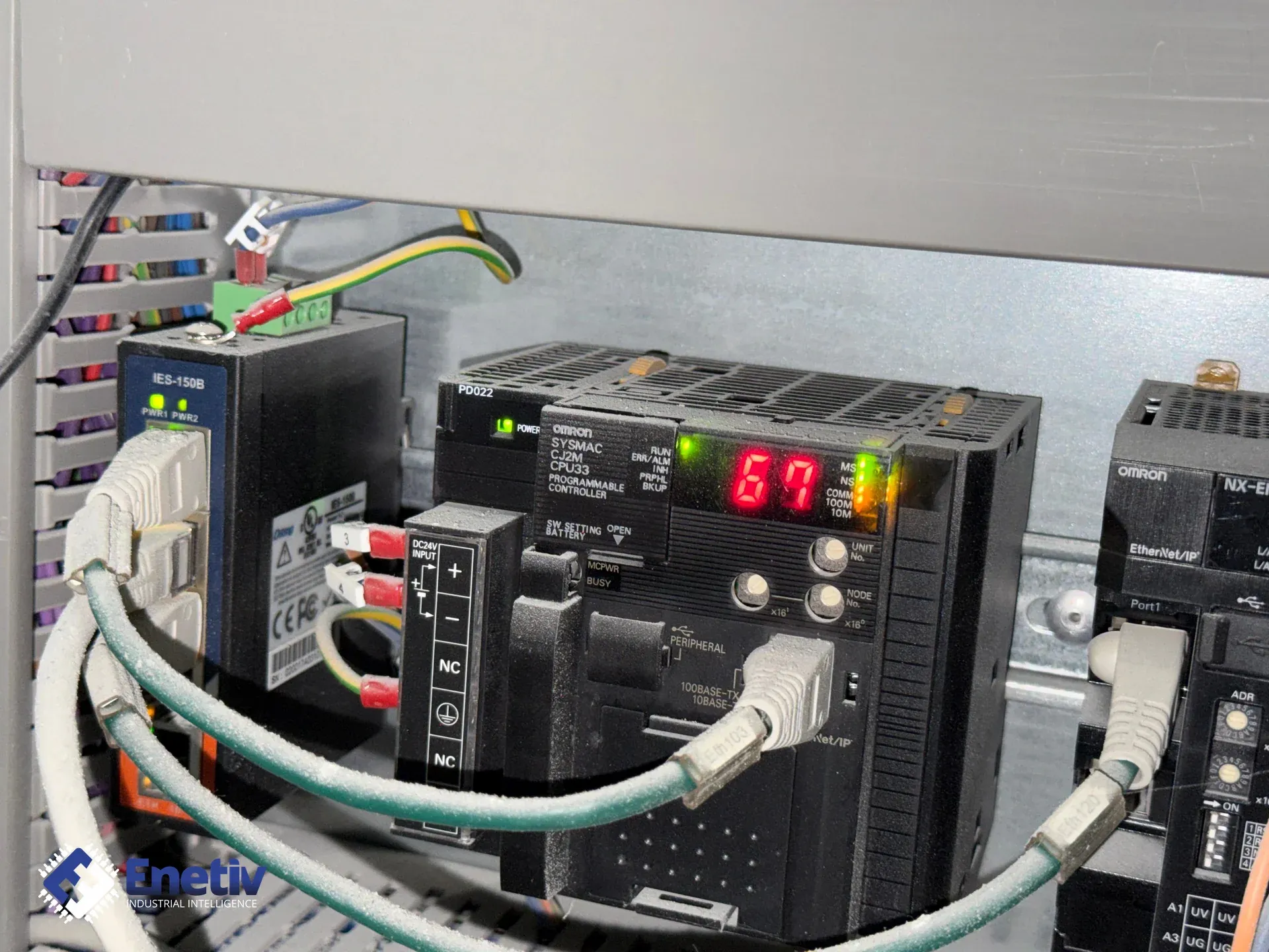
Loss of communication with a PLC brings production to a halt. Before you start looking for a software error, check the hardware layer first. See a step-by-step guide to diagnosing power supply, cables, and modules.
No Communication with the PLC – How to Rule Out Hardware Faults Step by Step
Loss of communication with a PLC can bring a machine or an entire production line to a standstill. While diagnostics often start by suspecting a program error, device configuration, or network parameters, it's worth starting with the hardware layer instead.
Cables, connectors, power supply, communication modules, and electromagnetic interference are all elements that can be checked even before starting diagnostics in TIA Portal, Studio 5000, or TwinCAT.
Below is a systematic diagnostic path to rule out the most common hardware faults step by step.
Step 1: LED Indicator and Power Supply Diagnostics
The first step should be analyzing the LED indicators on the CPU, communication modules, and I/O islands, such as Siemens SIMATIC ET 200SP or Allen-Bradley Point I/O.
The meaning of each indicator depends on the manufacturer and specific device model, so it's always worth comparing the observed state against the documentation for that particular controller or module.
Example Diagnostics in a Siemens SIMATIC Environment
In controllers and systems such as the S7-1500, S7-1200, or S7-300, you may encounter the following indicators, among others:
SF – System Fault
May indicate a system error, a hardware problem, a configuration mismatch, or a module failure.
BF – Bus Fault
May indicate a bus communication problem, for example on a Profibus DP or Profinet network. The cause could be a broken cable, lack of physical connection, a network device issue, or a configuration error.
Example Diagnostics in a Rockwell Automation / Allen-Bradley Environment
Systems such as ControlLogix or CompactLogix commonly use these indicators:
MS – Module Status
Indicates the module's state and diagnostics. Depending on the device, specific blink patterns may indicate a hardware fault or an issue requiring diagnostics.
NS – Network Status
Indicates the state of network communication, for example on EtherNet/IP or DeviceNet. The indicator may signal a lack of active connection, a communication timeout, or a network configuration problem.
Checking the Power Supply
Before further diagnostics, measure the supply voltage directly at the device's terminals.
For 24 V DC installations, it's worth checking not just whether voltage is present, but also its stability. Momentary drops, loose connections, an overloaded power supply, or installation issues can cause devices to restart or communication modules to malfunction.
| LED Indicator / Symptom | Possible Hardware Cause | First Diagnostic Action | Useful Tool |
|---|---|---|---|
| BF / NS – communication fault indicator | Damaged cable, connector, port, no physical connection, or a network device issue | Visual inspection of cables and connectors, and checking port status | Flashlight, network tester, multimeter |
| SF / MS – module fault indicator | Issue with the module, power supply, internal bus connection, or the electronics itself | Check module seating and power supply, then a controlled restart per manufacturer procedure | Visual inspection, multimeter, device documentation |
| No indicator at all | No power, damaged cable, fuse, terminals, or power supply | Measure voltage directly at the device | Multimeter |
Step 2: Cables, Connectors, and Network Topology
Cables operating in harsh industrial conditions are especially prone to damage. Vibration, machine movement, lubricants, high temperatures, and repeated flexing in cable carriers can damage insulation or break conductors.
For Profinet and EtherNet/IP networks, pay particular attention to:
- Cable condition
- RJ45 and M12 connectors
- Latches and mechanical fastening of connectors
- Condition of switch and device ports
- Points where cables pass through moving elements
For Profibus DP and RS-485-based communication, additionally check:
- Correctness of cable connections
- Condition of D-Sub connectors
- Shielding
- Termination settings in line with the bus topology
- Cable continuity between successive devices
Most Common Physical Layer Faults
| Communication Standard | Typical Connectors and Cabling | Typical Hardware Fault | Verification Method |
|---|---|---|---|
| Profinet / EtherNet/IP | RJ45, M12, industrial Ethernet twisted pair | Cable damage, chafing, loose connector, or damaged port | Visual inspection, checking link indicators, and cable testing with an appropriate tester |
| Profibus DP | D-Sub 9 and bus cable | Termination issue, cable or connector damage | Checking termination settings, visual inspection, and measurements per system documentation |
| Modbus RTU / RS-485 | Device-dependent connectors and bus cable | Broken cable, reversed polarity, missing or incorrect termination | Checking connections and physical layer parameters |
If cable damage is suspected, it's especially helpful to observe cable behavior while the machine is running. If communication drops only at a specific position of a moving element, it's worth carefully inspecting the cable inside the cable carrier.
Step 3: Shielding and Electromagnetic Compatibility
If communication drops randomly, especially when starting motors, inverters, or other high-power equipment, electromagnetic interference should be considered.
Potential issues can arise when communication cables are routed very close to motor power cables, inverter cables, or other interference sources.
It's worth checking:
- How cables are routed
- Shielding condition
- Correct grounding per manufacturer requirements
- Equipotential bonding between installation elements
- Condition of shield terminals
- Whether the cable used complies with the requirements of the specific industrial network
The method of connecting the shield depends on the type of installation, the communication standard, and manufacturer recommendations. There is no single universal method for all systems. For EMC issues, always follow device documentation and the design principles of the specific installation.
Step 4: Verifying Modules and the Internal Bus
If the power supply, cables, and external connections show no issues, the next step is to check the modules themselves.
In modular systems, it's worth checking:
- Correct module seating
- Contact condition
- Presence of contamination or signs of corrosion
- Condition of base elements and internal bus connections
- Any signs of overheating or mechanical damage
Before removing modules, disconnect power and follow the device manufacturer's procedure.
If an identical, working module is available, a controlled cross-test can be performed — swapping the suspected element for a known-good one. This method allows much faster confirmation of whether a specific module is the source of the problem.
Recommended Diagnostic Sequence
To minimize troubleshooting time, it's worth following a simple sequence:
- Check the LED indicators.
- Measure the supply voltage directly at the device.
- Check the cables and connectors.
- Verify the physical network connection.
- Inspect cable carriers and areas exposed to movement.
- Assess the impact of electromagnetic interference.
- Check module seating and the internal bus.
- Perform a controlled module swap, if available.
Only after ruling out basic hardware issues should you move on to configuration and software diagnostics.
Preventive Inspection Schedule
Regular inspections help catch problems before they lead to unplanned downtime.
| Installation Area | Example Frequency | Service Action | Purpose |
|---|---|---|---|
| Cable carriers and moving routes | Every 3 months | Inspect cables for chafing, cracks, and mechanical damage | Early detection of cable damage |
| Industrial M12, D-Sub, and RJ45 connectors | Every 6 months | Check fastening, mechanical condition, and contamination | Reduce issues from vibration and loose connections |
| 24 V DC power supply | Per maintenance schedule | Check voltage, terminals, and power supply load | Detect unstable power supply issues |
| Control cabinets | During planned shutdowns | Check temperature, contamination, ventilation, and electrical connections | Reduce risk of overheating and electronics failure |
| Communication modules and PLCs | Per TPM schedule | Check diagnostic indicators and physical device condition | Early detection of abnormalities |
Summary and Expert Help from Enetiv
Systematically ruling out faults at the physical layer can significantly shorten diagnostic time. It's worth starting with the simplest elements — power supply, LED indicators, cables, and connectors — before moving on to more advanced configuration and software analysis.
If the problem persists after checking the basic elements, the cause may be a damaged communication module, port, controller electronics, or power supply.
Enetiv offers industrial electronics diagnostics and support with component replacement and selection. For PLC and automation device communication issues, it's worth starting with a precise identification of the symptom and the model of the faulty device.
Having a PLC communication problem that basic diagnostics hasn't resolved? Prepare the controller model, communication module, and a description of the LED indicators — this information will help speed up further diagnostics.