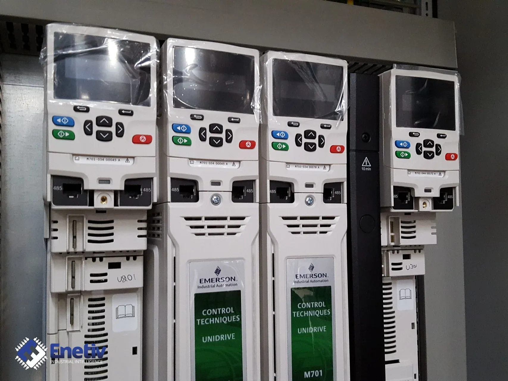
Inverter does not start or shows an error – repair of Control Techniques Unidrive (M701, M701-034 00045 A): reading the nameplate, diagnosing the error on the display, checking the RS485 ports and power supply
Files to download
Before you change anything in the parameters or wiring of a Unidrive M701, find the cause: read the nameplate, record the message from the display and check the power supply and the enable signal.
Inverter does not start or shows an error – repair of Control Techniques Unidrive (M701, M701-034 00045 A): reading the nameplate, diagnosing the error on the display, checking the RS485 ports and power supply
The Unidrive M701 inverter with catalogue number M701-034 00045 A works in machines as a high-performance drive for induction and servo motors, and when it does not start or an error appears on the display, it is easy to begin with changes to parameters and wiring. However, before you touch anything in the drive, you need to establish the cause: read the nameplate, write down the message, and check the power supply and the enable signal. Diagnostics carried out this way save time and do not destroy the traces that show what really happened.
Reading the nameplate
The designation M701-034 00045 A is read according to the scheme aaaa-bbc ddddde, in which the first element is the series, the second the frame size, and then the voltage, current and drive format. In this number, M701 denotes the series, 03 the frame size, and the digit 4 the voltage of 400 V, so it is immediately clear what supply the drive is intended for. Next, 00045 is the current designation, and the last letter A describes the drive format: according to the key, it means a 6-pulse rectifier with an inverter and an internal choke.
The supply for this version is 380/480 V AC ±10 %, and it is against this range that the measured supply voltage is compared. For M70x-03400045A in Heavy Duty mode the current is 4.5 A, the power 1.5 kW, that is 2 HP. For M70x-03400045A in Normal Duty mode the current is 6.2 A, the power 2.2 kW, that is 3 HP. The set of values depends on the nature of the load: HD is heavy load, ND normal, so before assessing whether the drive is matched to the machine, you need to establish which mode it works in.
While reading it, it is worth writing down the full designation from the nameplate, the serial number and the hardware and software version from the labels, and also taking photos of the nameplate and the connectors. You should also note what the drive is used for and what supply it has, because these data are needed when enquiring about a part or a repair.
Diagnosing the error on the display
Before clearing anything, you should write down the exact message visible in the upper left corner of the display and the state of the drive, and then establish whether we are dealing with a trip or only with an alarm. A drive that has tripped no longer controls the motor, whereas an alarm is a warning and the drive may still run, so these two cases require different handling.
A good example is the "Drive overload" alarm, that is, drive overload: it means the drive is overheating and refers to parameter 07.036, that is, the percentage of the thermal trip threshold. The value of this parameter shows how close to the thermal trip the drive is operating, so before a reset it is worth reading it and writing it down. If parameters were changed, saving parameters is performed after the change, and only then the reset.
A separate matter is terminal 31, which in the M70x series is the Safe Torque Off input (drive enable), that is, the enable for the drive to run. This description is general for the series, so the terminal assignment for a specific unit should be confirmed on the terminal diagram in the manual. According to the general Safe Torque Off principle, when the STO input is not energised, the drive is not enabled, which by itself explains the lack of start.
RS485 port and power supply
The EIA 485 serial port in the M701 is used for communication with the master controller, and the minimum connections are pins 2, 3, 7 and the shield. With fewer connections, communication should not be expected, so a lack of response on the link often simply means a broken or unconnected shield wire or one of these pins.
The manufacturer warns that accidentally connecting an Ethernet network adapter to the EIA 485 port of the M701 drive creates a low-impedance load. The sockets look similar, so before plugging in the cable you must check which socket it goes into.
The drive supply should be within the range of 380/480 V AC ±10 %. The check starts with inspecting the connectors and contacts, then the LEDs and the version markings on the housing are checked, and finally the supply voltage and the control voltage are measured.
What to watch out for when testing
- RS485 port and Ethernet: mixing up the sockets loads the drive port with a low impedance, so before plugging in the cable you must confirm the socket.
- A trip that came back: an error cleared after saving or a reset without noting the cause will appear again, and the trace of the original cause will be lost.
- Unsaved parameter changes: changes without saving are lost after the power is switched off, which looks like a recurring fault.
- Default settings: loading them erases your own configuration and may change the drive's operating mode, so a parameter backup is made first.
- Terminal 31 (STO): an open input is sometimes taken for a drive fault, although it is what blocks the start.
- Input and output signals: a calibrator or a current source is suitable for checking them, which makes it possible to rule out an error in the signal circuit.
- Origin of parts: you should document where the drive or part comes from, together with the nameplate data and photos.
How the check proceeds
- Writing down the nameplate data: the full designation, serial number and hardware and software version.
- Inspecting the connectors, contacts, LEDs and markings on the housing.
- Reading the message and the state of the drive, distinguishing a trip from an alarm, and noting parameter 07.036 in the case of the "Drive overload" alarm.
- Measuring the supply voltage against the range of 380/480 V AC ±10 % and the control voltage, and also checking terminal 31.
- Checking the RS485 port for the connections 2, 3, 7 and the shield, and for the correct socket.
- Making a parameter backup before any change.
- Reset and observing whether the message returns.
If after the reset the drive starts and the message does not return, the cause was usually a momentary overload, a missing enable or the power supply. When the same message appears again, and the power supply and terminal 31 are fine, the noted message, the nameplate data and the photos should be handed over for repair.
Frequently asked questions
How do I read the type designation M701-034 00045 A?
M701 is the series, 03 the frame size, 4 the voltage of 400 V, 00045 the current designation, and the letter A the drive format: a 6-pulse rectifier with an inverter and an internal choke.
Does the drive not start because of a fault if terminal 31 is open?
Not necessarily, because with an unenergised STO input the drive is in principle not enabled, so you first need to confirm the state of this input on the terminal diagram.
Enetiv works in industrial automation from two sides: we supply parts and we repair them. We have new, used and refurbished parts from brands including Allen-Bradley (Rockwell Automation), Siemens, Schneider Electric, Bosch Rexroth and ABB, we diagnose and repair inverters, servo drives, I/O modules and controllers, we service motors and servomotors, with our own warranty on repairs. We also specialize in end-of-life (EOL) parts and service, including older-generation and unusual components. Please contact us at https://enetiv.com/zapytanie.
Sources
- UNIDRIVE M700 UNIDRIVE M701 - Nidec
- Frame 3 to 11 Unidrive M700/ - Nidec
- Unidrive M700_M701 and HS70-71 Control GSG Issue4.book Page 1 Monday, December 19, 2022 9:25 AM - Nidec
- Control User Guide Unidrive M700 - Galco
- UNIDRIVE M700 Manufacturing Automation drive - Vfds
Publication date: 20.11.2026