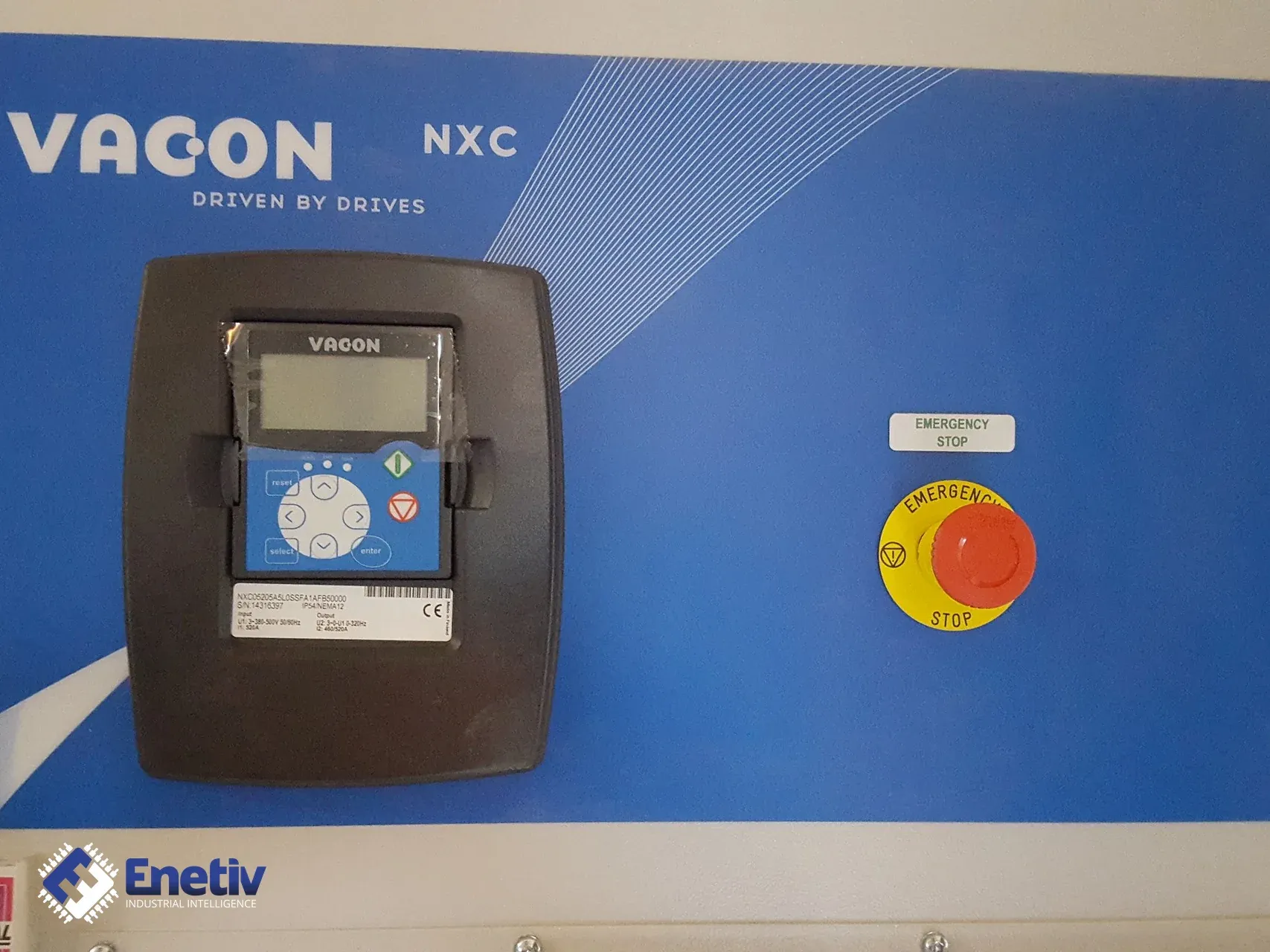
How to read the nameplate of a Vacon NXC inverter (NXC05205A5L0SSFA1AFB50000) – type code, serial number, input and output data, control panel; used unit
Files to download
For a used inverter, the nameplate is the only specification of the unit. See how to break the Vacon NXC type code into segments, what to copy from the nameplate and what to check before commissioning.
How to read the nameplate of a Vacon NXC inverter (NXC05205A5L0SSFA1AFB50000) – type code, serial number, input and output data, control panel; used unit
A cabinet-type inverter, that is, a frequency converter, stands in a switchgear room or on the shop floor next to the driven machine: on one side it takes voltage from the supply network, on the other it powers the motor, and along the way it works with the control system through inputs and outputs and communication cards. The nameplate is the only place where it is recorded what exactly a given unit is, and for a second-hand device, without an order history, it replaces the specification. If you are buying or commissioning a used Vacon NXC with the designation NXC05205A5L0SSFA1AFB50000, you need to break this code down into its segments, copy the data from the nameplate into the documentation and link it to the drive parameters.
How to read the type code
The designation NXC05205A5L0SSFA1AFB50000 consists of several segments, each describing a different feature. The first is the NXC family, that is, the Vacon NXC series: free-standing inverters built into cabinets, intended, according to the Vacon NXC user manual, for a wide power range. Next comes the number 0520, describing the drive size, and the current and power values must be read directly from the nameplate of the unit.
Three characters of the SSF group matter; in the Vacon NXC user manual (a Danfoss document) they describe the hardware version of the drive. The table below lists them in the order in which they appear in the code.
| Position in the SSF group | Character | Meaning |
|---|---|---|
| Supply (first letter) | S | 6-pulse connection |
| Mounting (second letter) | S | air-cooled drive |
| Boards (third letter) | F | standard boards |
In practice this means that the unit has a 6-pulse supply arrangement, not a 12-pulse or regenerative variant, so when selecting the supply, chokes and cabling you must not assume features of other variants of the series. Air cooling indicates that the condition of the drive depends on the cleanliness of the ventilation and the efficiency of the fans, and the letter F tells us about standard boards, not boards in a special version.
The characters A, 5, L and 0, standing between the number 0520 and the SSF group, have no confirmed meaning for this code in the documents we use, so we do not interpret them and do not guess. Nor should their meanings be carried over from the designations of other series or from memory, because a wrong reading of the voltage or enclosure class ends in a wrong selection of protection. The string A1AFB50000 at the end of the code confirms only that the final characters denote option board slots. What is actually installed in the slots is determined by inspecting the unit and by the nameplate record, not by the inscription alone.
What to read from the nameplate and how it relates to parameters
Three things should be copied from the inverter nameplate: the full type designation, the serial number, and the input and output data. The full type code serves to identify the version and to compare it with the record in the machine documentation, the serial number unambiguously ties the specific unit to its history, and the input and output data show for what supply network and what load the drive is intended. For a used device all three items are copied literally, without abbreviations and without correcting legibility, because any mistake in a single character changes the identification of the drive.
The drive nameplate data do not replace the motor data. According to the quick start guide from the Vacon NX technical documentation (a Danfoss document), all parameters have default values set at the factory, and for correct operation of the drive the data from the motor nameplate must be checked and the corresponding motor parameters entered. This concerns the nominal voltage, nominal frequency, nominal speed, nominal current and nominal cosϕ. The same guide indicates that the parameters of group G2.1 are to match the data from the nameplate, so after taking over a used inverter, the settings stored in it are first compared with the nameplate of the motor that is actually connected to it. It happens, after all, that the drive came from another machine and carries settings for a different motor.
A separate matter is the control inputs. According to the Vacon NXC documentation, there are 6 digital inputs, they work in positive or negative logic and require a voltage of 18…30 V DC. The practical meaning is simple: the control signal from a PLC, button or relay must fall within this range, because below its lower limit the input will not recognise the active state, and a value outside the range may be read incorrectly. When changing the logic from positive to negative, you must therefore anticipate how the whole control system will behave.
It is also worth remembering the warning from the documentation: if the start signal is active at the moment voltage is applied, the motor may start, and the control logic of the inputs and outputs, including the start, may change after a change of parameters, application or higher-level system. When commissioning a unit with an unknown history, the control of the inputs and outputs is disconnected wherever an unexpected start would risk an accident.
Control panel
The panel is the first point of contact with a used drive, so it is good to know what may be read from it without interfering with the settings. The panel language is selected in the main menu M6, on page 6.1 (according to the quick start guide from the Vacon NX documentation, a Danfoss document). If the Startup Wizard is active, the language and application are selected in its first steps and confirmed with the Enter button, and if the wizard is disabled, the language is set in M6 on page 6.1, and the application on page 6.2.
The second thing worth remembering is fault signalling: according to the Vacon NXC documentation, the red LED on the panel starts to blink when a fault is displayed. For a unit obtained from another installation, blinking of this LED right after the first power-up indicates an active fault, which must be recorded and diagnosed before the drive is connected to the motor. Recording the message from the screen verbatim, together with its code, facilitates later analysis.
What to watch for during replacement (used unit)
When replacing or taking over a used inverter, everything is checked in a fixed order, and the results are recorded as you go. Before any work on an open cabinet, the rule from the documentation applies: after switching off the power you must wait until the cooling fan stops and the LEDs on the panel go out, and then another 5 minutes, because the internal components are at mains potential, and the cabinet door must not be opened earlier. The control terminals may moreover be at a dangerous voltage even after the drive is disconnected from the mains, so the absence of voltage on them is checked before touching.
- Inspection of the cabinet and terminals: checking that there are no signs of flooding, dust, overheating, discolouration of insulation or loose wires.
- Checking the condition of connectors and contacts: assessing whether there is no corrosion, melting, cracked housings or traces of earlier repairs.
- Comparing the nameplate with the designation on the enclosure and with the hardware and software version labels: consistency of the type code in all places is basic proof that the cabinet and its contents come from the same unit.
- Taking photos of the nameplate and connectors before disconnecting any wires, so that the later connection can be recreated without guessing.
- Recording the origin of the unit: what machine or installation it comes from, in what conditions it operated and why it was dismantled.
- Making a copy of the parameters before changes, so that in the event of an incorrect setting it is possible to return to the initial state.
- Checking the values of inputs and outputs with a calibrator or a current source: readings on the analog inputs and the states of the digital inputs are compared with the reference value, and the digital inputs are verified in the range of 18…30 V DC.
For the documentation of the unit, prepare the full type designation, the serial number, the hardware and software versions and photos of the nameplate. Such a set later allows you to unambiguously reconstruct what drive was installed and to compare it with the machine documents. At the same time, you must not assume interchangeability with other variants of the series or infer it from the mere coincidence of a few characters of the code.
Questions and answers
Can the power and current of the drive be read directly from the type code?
The code contains the number 0520, describing the drive size, but the rated values must be read from the nameplate of the unit and recorded in the documentation.
Does the ending A1AFB50000 tell which cards are in the drive?
The final characters denote option board slots and do not guarantee what is actually installed in them. The contents of the slots are confirmed by inspecting the cabinet after waiting the required time after disconnecting the power, and the cards found are recorded together with photos.
Enetiv works in industrial automation from two sides: we supply parts and we repair them. We have new, used and refurbished parts from brands including Allen-Bradley (Rockwell Automation), Siemens, Schneider Electric, Bosch Rexroth and ABB, we diagnose and repair inverters, servo drives, I/O modules and controllers, we service motors and servomotors, with our own warranty on repairs. We also specialize in end-of-life (EOL) parts and service, including older-generation and unusual components. Please contact us at https://enetiv.com/zapytanie.
Sources
- vacon nxp/c AC DRIVES - Danfoss
Publication date: 19.11.2026