Expanding a Legacy Omron CJ2M-CPU33 System with Remote I/O on EtherNet/IP (NX-EIC202) – A Practical Guide
Files to download
How to connect an NX-EIC202 EtherNet/IP Coupler and NX-series modules to an existing Omron CJ2M-CPU33 controller without replacing the whole system – architecture, tools (CX-Programmer, Sysmac Studio, Network Configurator), connection limits, and step-by-step configuration.
Expanding a Legacy Omron CJ2M-CPU33 System with Remote I/O on EtherNet/IP (NX-EIC202) – A Practical Guide
Many industrial plants want to keep their existing Omron CJ2M-CPU33 controller while taking advantage of modern NX-series I/O modules. This article explains how to safely and effectively connect an NX-EIC202 EtherNet/IP Coupler and selected NX-series I/O Modules, avoiding a costly replacement of the entire system.
Why upgrade the Omron CJ2M-CPU33 instead of replacing the whole controller?
Cost and operational benefits of keeping the existing CPU
Keeping the CJ2M-CPU33 eliminates the need to rewrite the entire PLC program, which in practice saves engineering time and software licensing costs. Thanks to its built-in EtherNet/IP port, you can add modern remote I/O without migrating to the NJ/NX platform, while keeping your existing OB/FB/FC blocks, ANY-type indicators, and classic architecture. The CJ2M-CPU33 offers 20K-step program capacity, 2560 I/O max, and 64K data memory (DM: 32K words / EM: 32K words × 1 bank) – verified against the manufacturer's official specification – which is sufficient for most retrofit applications.
What does the hardware architecture look like when connecting NX-series modules to the CJ2M-CPU33?
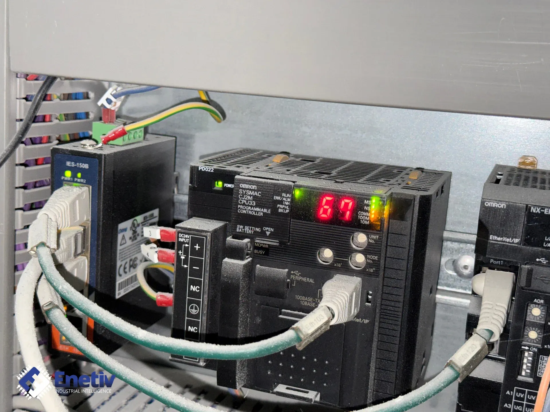
Connection layout: CJ2M-CPU33, Ethernet switch, NX-EIC202 coupler, and I/O modules
A typical retrofit topology consists of four main elements: the CJ2M-CPU33 (with a built-in EtherNet/IP port and up to 2560 I/O), an industrial Ethernet switch (e.g., 100 Mbit, VLAN support), the NX-EIC202 acting as a bridge between the EtherNet/IP network and the NX I/O bus, and selected NX-series I/O Modules (e.g., DI, DO, AI, AO). Each NX module connects to the power and signal bus in the coupler, and the coupler communicates with the CPU via CIP Class 1 tag data links. The CJ2M-CPU33 provides one RS-232C/485 option port and a USB programming port, which simplifies diagnostics and firmware updates.
Power planning: unit power supply vs. I/O power on the NX bus
In the retrofit architecture, there are two power sources to consider:
- Unit Power Supply – powers the CPU and coupler themselves (typically 24V DC, 2 A).
- I/O Power Supply – powers the connected NX modules (e.g., 24V DC, 5 A depending on the sum of the modules' currents).
It's important to select an NX-PDxxxx power supply with appropriate resistance and filtering, ensuring minimal noise and compliance with IEC 61800-5-1.
What programming tools are needed to integrate the CJ2M and NX-EIC202?
CX-Programmer (CX-One) for programming the CJ2M-CPU33
To edit and compile the PLC program in the classic CX-Programmer environment, we use the version bundled in the CX-One package. This tool allows you to define the I/O table, create tags, and configure the EtherNet/IP port (TCP/IP tab). In the PLC I/O Table window, the built-in port appears as CJ2M-EIP21, where you can set the IP address and subnet mask.
Sysmac Studio (Standard or I/O Edition) for configuring the coupler and NX modules
The NX-EIC202 and connected NX modules are configured in Sysmac Studio. In I/O Edition mode, you can define "slices" – logical divisions of the bus – assign node addresses, and generate the EDS (Electronic Data Sheet) file needed for registration in Network Configurator. The NX-EIC202 opens under Configurations and Setup → EtherNet/IP in Multiview Explorer.
Network Configurator for creating tag data links (CIP Class 1)
After generating and importing the EDS file, Network Configurator is used to define tag data links, which map PLC variables to I/O addresses in the coupler. This solution uses CIP Class 1 communication (Implicit Messaging) – the most efficient method for real-time data exchange.
What are the key technical limitations and pitfalls when connecting the CJ2M-CPU33 to the NX-EIC202?
EtherNet/IP connection limits on the CJ2M-CPU33
According to the manufacturer's official datasheet (CSM_CJ2M-CPU3-CPU1_DS), the built-in EtherNet/IP port on the CJ2M-CPU33 supports a maximum of 32 tag data link connections (not 8, as is sometimes incorrectly stated). Exceeding this limit results in dropped packets and errors in the I/O table.
Generating and registering the EDS file in Sysmac Studio, and firmware version requirements
Registering the EDS file and supporting CIP Class 1 tag data links requires a sufficiently up-to-date NX-EIC202 coupler firmware version. In the publicly available documentation, we were unable to conclusively confirm a specific minimum version number (e.g., "V1.04") as a universal threshold for this feature – these requirements are periodically updated across manual revisions (Cat. No. W536). We recommend always checking the coupler's current firmware version in Sysmac Studio (Unit Version tab) and comparing it against the requirements described in the latest edition of the NX-series EtherNet/IP Coupler Unit User's Manual (W536) before starting integration.
I/O refresh time and impact on the PLC scan cycle
According to the verified specification, the packet refresh interval (RPI) for the CJ2M's built-in EtherNet/IP port is configurable from 1 to 10,000 ms (in 0.5 ms increments) independently for each connection, and the permissible communications bandwidth is up to 3,000 packets per second (pps). In practice, with a large number of NX modules, pay attention to the impact on the CJ2M-CPU33 scan cycle (typically 2-5 ms) and choose an RPI that is as short as possible while still matching real application requirements – an overly aggressive RPI setting with many active connections can burden both the network and CPU processing time.
How to configure the Omron CJ2M-CPU33 retrofit with NX modules, step by step?
Configuration workflow – from EDS export to tag definition in CX-Programmer
The table below outlines the detailed, six-step integration process.
| Step and phase name | Programming tool | Critical actions and parameters | Common error / pitfall |
|---|---|---|---|
| 1. Prepare the project in Sysmac Studio | Sysmac Studio I/O Edition | Create a new project, add the NX-EIC202, configure the node address (e.g., 0x01) | Incorrect node address – conflict with another device |
| 2. Define slices and assign NX modules | Sysmac Studio | Set up slices (e.g., Slice 1 – DI, Slice 2 – DO), specify channel counts | Channel count mismatch with actual hardware configuration |
| 3. Export the EDS file | Sysmac Studio | Select "Export EDS", save as NX-EIC202.eds | Exporting with outdated firmware – missing certain objects |
| 4. Import the EDS into Network Configurator | Network Configurator | Import the file, create a new network project, add the CJ2M-CPU33 | Registration failure – incompatible EDS format |
| 5. Define tag data links (CIP 1) | Network Configurator | Map PLC variables to I/O addresses (e.g., %MW100 ↔ DI 1.0) | Transfer errors – incompatible tag configuration |
| 6. Transfer the configuration and test the connection | CX-Programmer + Network Configurator | Upload the project to the CJ2M-CPU33, run "Transfer PC to Unit", check status in the "EtherNet/IP" tab | No communication – mismatched subnet mask |
What are the best practices and diagnostic tips for commissioning the EtherNet/IP network?
Resolving common connection errors and node address conflicts
The most common causes of problems are:
- Duplicate IP addresses – make sure every device has a unique address on the same subnet (e.g., 192.168.250.1 with mask 255.255.255.0).
- Incorrect Unit Number in the CJ2M configuration – it should match the coupler's node number.
- Incompatible firmware – always check the current NX-EIC202 firmware version in Sysmac Studio and compare it against the requirements in the W536 manual before exporting the EDS.
Ensuring network stability: topology, priorities, and noise isolation
The recommended topology is a star configuration with a managed switch (e.g., 100 Mbit, QoS support). Set VLAN priority 2 for CIP 1 traffic to minimize latency. In addition, use shielded twisted-pair cables (Cat 6) and filtering separators on the power line to reduce electromagnetic interference.
Comparing communication methods: Implicit vs. Explicit Messaging
Implicit Messaging (CIP Class 1) provides a constant, deterministic data flow with minimal latency, ideal for fast control signals. Explicit Messaging (CIP Class 3/UCMM) is used for configuration and diagnostics but is not suitable for real-time data exchange. The CJ/CJ2 EtherNet/IP Units Operation Manual describes both methods, along with tag data links and FINS communications, for the CS1W-EIP21, CS1W-EIP21S, CJ1W-EIP21, and CJ1W-EIP21S families.
| Criterion | Implicit Messaging (CIP Class 1 – Tag Data Links) | Explicit Messaging (CIP Class 3 / UCMM) |
|---|---|---|
| Real-time performance | Configurable cycle (RPI) 1-10,000 ms, low latency with a short RPI | Variable, request-dependent |
| Configuration complexity | Requires EDS and tag data links | Simpler – only requires an IP address and port |
| Data size limits | Depends on configuration and number of connections (max. 32 for the CJ2M's built-in port) | Up to 2 KB per request |
| Memory allocation in CJ2M | Reserves memory for tag tables | Uses temporary buffers |
| Best use case | Control cycle, fast I/O | Configuration, diagnostics, service |
Power planning for the NX coupler bus
| Power category | Voltage and required current | Calculation method / required hardware module | Key safety and noise-immunity notes |
|---|---|---|---|
| Unit Power Supply | 24V DC, 2 A (minimum) | Select a 24V DC power supply, check ±10% tolerance | Use EMI filters, connect to the control cabinet ground |
| I/O Power Supply | 24V DC, 5-20 A (depends on modules) | Sum of currents of all NX modules + 20% margin | Separate power supply for I/O, separate power and signal wiring |
Summary and next steps
Retrofitting the Omron CJ2M-CPU33 with the NX-EIC202 and NX-series modules is an effective way to modernize without a full controller replacement. The key elements are: keeping the CPU's built-in EtherNet/IP port (with a limit of 32 tag data link connections), correctly configuring IP addresses and the subnet mask (e.g., 192.168.250.1 / 255.255.255.0), exporting and registering the EDS file, and defining tag data links in Network Configurator. Remember to check and, if necessary, update the NX-EIC202 firmware in line with the current edition of the W536 manual, plan power correctly, and test network stability before deploying to production.
If you're looking for a full range of industrial automation products – from Omron controllers, to Allen-Bradley components, Danfoss devices, and ABB solutions – we invite you to explore our offering. Enetiv is a distributor of leading brands with attractive discounts and technical support. Contact us at enetiv.com/contact for a quote and consultation on your retrofit project.
Sources
- Omron – CJ2M-CPU3[]/CPU1[]/MD21[] CPU Units, datasheet (memory, I/O, EtherNet/IP port specification, 32 tag data link connection limit): https://www.ia.omron.com/products/family/2712/specification.html
- Omron – SYSMAC CJ2M CPU Units, datasheet (Mouser): https://www.mouser.com/datasheet/2/307/-532203.pdf
- Omron – NX-EIC202 NX-series EtherNet/IP Coupler Unit, datasheet (unit version, RPI, module count): https://files.omron.eu/downloads/latest/datasheet/en/nx-eic_nx-series_ethernet_ip%E2%84%A2_coupler_unit_datasheet_en.pdf?v=2
- Omron – NX-series EtherNet/IP Coupler Unit User's Manual (W536), for verifying the current firmware version: https://www.omron-ap.com/products/family/3412/download/manual.html
- Omron – CJ1W-EIP21/EIP21S CJ-series EtherNet/IP Unit, datasheet (Implicit/Explicit Messaging, tag data links): https://files.omron.eu/downloads/latest/datasheet/en/cj1w-eip21_eip21s_ethernet_ip_unit_datasheet_en.pdf?v=1762493002