Siemens SIRIUS 3RT10 Contactor and Pilz PNOZ s7 Safety Relay Won't Energize the Coil – Contact Wear Causes and Safety Category Faults (Cat. 3/4 per EN ISO 13849)
Files to download
The line won't start and the PLC reports no fault? A diagnostic guide to a locked-out EDM safety loop between the Siemens SIRIUS 3RT10 contactor and the Pilz PNOZ s7 relay — distinguishing a physical fault (contact wear/welding) from a Category 3/4 logic fault under EN ISO 13849, a step-by-step diagnostic protocol, and preventive measures.
Siemens SIRIUS 3RT10 Contactor and Pilz PNOZ s7 Safety Relay Won't Energize the Coil – Contact Wear Causes and Safety Category Faults (Cat. 3/4 per EN ISO 13849)
Is your production line refusing to start when the start button is pressed, while the PLC reports no faults at all? The most common culprit is a locked-out safety loop – either a physical failure of the Siemens SIRIUS 3RT10 contactor or a logic fault in the Pilz PNOZ s7 module rooted in EN ISO 13849 requirements (Category 3 or 4). This guide explains how to tell the two apart, how to diagnose them, and how to prevent them.
Why won't the PNOZ s7 coil energize even though the PLC reports no errors?
In safety systems controlled by Pilz PNOZ s7, the output coil is only energized once the monitoring loop (EDM – External Device Monitoring) confirms that every element is in the correct state. If even one element – most commonly the Siemens 3RT10 contactor – fails to close its auxiliary contact, the loop stays open and the safety relay blocks the output, regardless of what the PLC reports.
Anatomy of the safety loop – physical vs. logic lockout
A typical PNOZ s7 and Siemens 3RT10 configuration uses:
- a main contactor (power contact), and
- an auxiliary N/C contact wired in series with the EDM loop.
If the auxiliary contact fails to return to its closed position (e.g. due to contact welding or wear), the "safe to reset" signal is never generated, and the PNOZ s7 keeps the coil de-energized. On the other hand, in a Category 3/4 architecture, redundancy and diagnostics are required – a single logic fault can also cause a lockout if it isn't detected in time. A physical EDM loop lockout differs from a logic lockout: in the first case, the device physically cannot close the loop (a welded contact); in the second, the safety logic withholds reset permission because it hasn't detected that a safe state has been restored.
How does the feedback loop (EDM) work together with the Siemens 3RT10 contactor?
The EDM loop monitors the physical state of the contacts via feedback signals wired to the Y1-Y2 terminals on the Pilz PNOZ s7 module. When the 3RT10 contactor energizes, its auxiliary N/C contact should close, closing the loop and allowing operation to continue. Mechanically linked contacts (mirror contacts) or N/C contacts wired in series form the feedback path that PNOZ s7 monitors to confirm that the main power contact has actually closed.
Terminal and signal states in the EDM loop
Typical topology:
- Terminals A1-A2 – exclusively the module's power supply (24 VDC / 0 V); they are not used for contact monitoring, and the contactor's auxiliary contact must not be wired to them.
- The 3RT10 contactor's auxiliary N/C contact is wired in series in the feedback loop, which runs to the PNOZ s7 module's Y1-Y2 terminals.
- The Y1-Y2 terminals serve as the measurement point – a "0 V" state means the loop is open, "24 V" means it's closed.
If the wiring is done incorrectly and A1 or Y1/Y2 are connected to the expansion module, the loop won't function properly – this is a common wiring mistake. The Pilz PNOZ s7 documentation explicitly warns: "Do not connect A1 and Y1/Y2 to the expansion module!" If a base unit and a PNOZsigma expansion module are linked via the dedicated connector, no additional wiring of these terminals is required or permitted – such wiring errors can completely disable the feedback loop.
What should you check in Scenario A – contact wear or welding on the contactor?
Physical wear on the Siemens SIRIUS 3RT10 contacts shows up as:
- the auxiliary N/C contact failing to close,
- elevated resistance when measured with a multimeter,
- abnormal LED signals on the PNOZ s7 module.
Diagnosing contact wear
- Disconnect power and isolate the contactor from the EDM loop.
- Measure the resistance between the N/C contacts and ground – the value should be < 1 Ω; higher readings suggest contact erosion.
- Visually inspect for signs of welding or burning.
- Replace the contactor if resistance exceeds the acceptable limit or if the contact fails to close mechanically.
Featured snippet: If the auxiliary N/C contact on the Siemens 3RT10 contactor is welded or worn, the EDM loop stays open, which means Pilz PNOZ s7 will not permit the coil to energize and the system remains locked out. A welded contact cannot return to its rest position, which blocks a reset of the safety loop.
How do you recognize a safety category fault (Cat. 3 vs. Cat. 4) in the PNOZ s7?
A Category 3 architecture uses two parallel channels with cross-monitoring. Category 4 requires full redundancy plus a diagnostic coverage (DC) of at least 99% – any inconsistent behavior between channels must be detected before the next demand on the safety function. Category 4 achieves PL e (Performance Level e), which roughly corresponds to SIL 3 (Safety Integrity Level 3) per the ISO 13849-1/IEC 61508 correlation tables, and represents the maximum level achievable under EN ISO 13849-1 or IEC 62061.
Comparing Cat. 3 and Cat. 4 requirements
Featured snippet: Category 3 detects a single fault through channel redundancy, while Category 4 additionally requires that every detected fault be flagged and that an accumulation of undetected faults never lead to loss of the safety function. In Category 3, a redundant structure with cross-monitoring between two active channels plus cyclic monitoring of the output device allows a single fault to be tolerated. In Category 4, a single fault must never lead to loss of the safety function and must be detected at or before the next demand; where detection isn't possible, an accumulation of undetected faults must not lead to loss of the safety function.
How do you diagnose the safety loop step by step?
Below is a detailed protocol for telling a physical cause apart from a logic one.
Diagnostic protocol
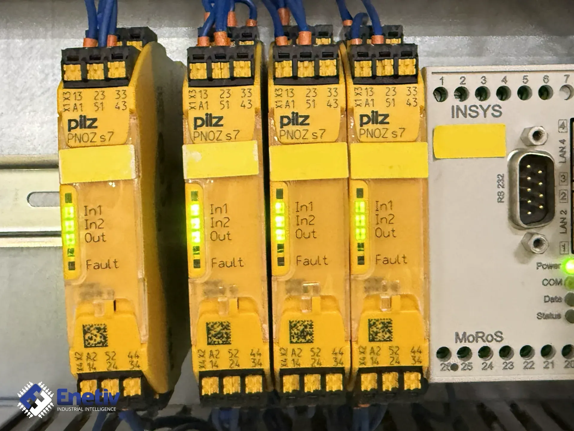
- Check the PNOZ s7 LEDs – read the combination of states (Power, In1, In2, Out, Fault). Full details on the codes are in the Pilz PNOZ s7 operating manual (keep the manufacturer's full document on hand).
- Verify the EDM wiring – use a multimeter to measure the voltage at the Y1-Y2 terminals with the contactor energized. It should read 24 V (or 0 V if the loop is open).
- Insulation test – with power disconnected, measure the resistance between the N/C contacts and ground; a value < 1 Ω indicates a good contact.
- Simulate a fault – manually open the N/C contact (e.g. using a test button) and observe the LED response and the PLC output state.
- Review PNOZ s7 logs – in the diagnostic software (e.g. Pilz SafeLogic), check the fault history and response times.
Featured snippet: To diagnose a safety loop lockout, first read the LED codes on the Pilz PNOZ s7, then measure the voltage at the Y1-Y2 terminals and check the N/C contact resistance on the Siemens 3RT10. If the loop won't close, the cause is physical; otherwise, look for logic faults in the Cat. 3/4 configuration.
What preventive measures should you implement to avoid a loop lockout?
Prevention requires both proper component selection and regular maintenance.
Design and component selection
- Use Siemens SIRIUS 3RT10 contactors with additional "mirror" auxiliary contacts – these detect welding of the main contact. Mechanically linked contacts should be routed to the safety relay's feedback loop.
- Add surge-suppression components (RC networks, varistors) per Siemens's recommendations (e.g. an RC snubber of 470 Ω / 470 nF as an indicative value) across the coil winding to reduce arcing and extend contact life – verify the exact selection against the Siemens SIRIUS documentation for the specific coil variant.
- Choose the safety category to match the application's requirements – if Category 4 is required, ensure full redundancy and DC ≥ 99% diagnostics.
- Monitor redundant contactors via the EDM loop – if a contactor fails to return to its rest position, the loop will stay open and block a restart.
Maintenance procedures
- Check N/C contact resistance every 6 months – replace if it exceeds 1 Ω.
- Perform functional tests of the EDM loop every 12 months using the test buttons on the PNOZ s7.
- Monitor the fault history in the Pilz software – a fast response to recurring warnings can prevent a failure.
Implementing these practices minimizes the risk of both physical contactor wear and safety-logic faults.
FAQ
Why won't the PNOZ s7 allow a reset after the E-stop button is released?
Because the EDM loop isn't closing – most commonly caused by an open or welded N/C contact on the Siemens 3RT10 contactor, which keeps the LED in the "Fault" state.
How do you tell a physical fault from a logic fault in a Cat. 3 system?
A physical fault shows up as the EDM loop failing to close (0 V at Y1-Y2) and a steady "Fault" LED code. A logic fault in Cat. 3 shows up as a mismatch between the two channels' signals with no physical failure present.
Can replacing a single contactor upgrade a system from Cat. 3 to Cat. 4?
No. Category 4 requires not just better components, but also full diagnostics (DC ≥ 99%) and compliance with additional EN ISO 13849-1 requirements that must be validated at the design level.
What are typical PNOZ s7 LED codes indicating an EDM loop problem?
Depending on the version, the combination Power = ON, In1 = OFF, In2 = OFF, Out = OFF, Fault = ON indicates an open EDM loop. Full details are in the Pilz PNOZ s7 operating manual.
Can you work around contact welding by increasing the control current?
No. Increasing the current doesn't remove physical welding and can make the situation worse. The contactor should be replaced, or a "mirror" contact that detects welding should be used.
What electrical parameters should an RC snubber for the 3RT10 contactor meet?
A typical indicative choice is 470 Ω resistance and 470 nF capacitance, but the exact selection depends on the coil supply voltage and cable characteristics – consult the Siemens SIRIUS documentation.
Where can I buy spare parts for Siemens SIRIUS 3RT10 contactors and Pilz PNOZ s7 modules?
Enetiv is a distributor of leading brands, including ABB, Danfoss, Siemens, and Pilz, offering competitive pricing on safety and automation components. For a quote and technical consultation, visit enetiv.com/contact.
Sources
- Pilz. "PNOZ s7 Operating Manual" (21399-EN-10) – power supply terminals A1/A2, feedback loop, warning against connecting A1 and Y1/Y2 to the expansion module: https://www.pilz.com/download/open/PNOZ_s7_Operat_Man_21399-EN-10.pdf
- Pilz. "PNOZ s7.1 Datasheet" – terminal configuration and expansion module: https://pim.galco.com/Manufacturer/Pilz/TechDocument/Data%20Sheet/pnoz_s7_1_dat.pdf
- Siemens. "SIRIUS 3RT10 Contactor Series – Technical Specifications." Product documentation covering auxiliary contacts and feedback requirements.
- ISO 13849-1:2015. "Safety of machinery – Safety-related parts of control systems – Part 1: General principles for design." Defines safety categories 3 and 4, redundancy and diagnostic requirements.
- IEC 62061:2021. "Safety of machinery – Functional safety of safety-related electrical, electronic and programmable electronic control systems." International standard on safety integrity levels.