WAGO 750-377, 750-352, 750-333, 750-306 – Comparing Communication Modules
Files to download
PROFINET, EtherNet/IP, PROFIBUS DP, or DeviceNet? Comparing WAGO 750-377, 750-352, 750-333, and 750-306 communication modules – connectors, addressing, LED diagnostics, and a practical replacement checklist.
WAGO 750-377, 750-352, 750-333, 750-306 – Same I/O Node, Four Different Networks: How to Choose the Right Communication Module?
Maintenance engineers, system integrators and procurement teams often confuse the WAGO-I/O-SYSTEM 750 node itself with its communication head. This guide explains why the choice between 750-377 (PROFINET), 750-352 (EtherNet/IP, Modbus TCP), 750-333 (PROFIBUS DP) and 750-306 (DeviceNet) directly affects installation correctness, diagnostics, and maintenance costs.
Why does choosing the right communication module matter when replacing a WAGO 750 node?
I/O modules in the WAGO 750 series are interchangeable – digital and analog "slices" fit any node. However, it is the fieldbus coupler (communication head) that defines the protocol, the physical interface, and the addressing method. Ordering just a "WAGO 750" risks mismatching an incompatible port (RJ-45 vs. a DeviceNet connector or D-sub) or misconfiguring the network, leading to downtime and extra costs.
What are the fundamental differences between the four WAGO 750 communication heads?
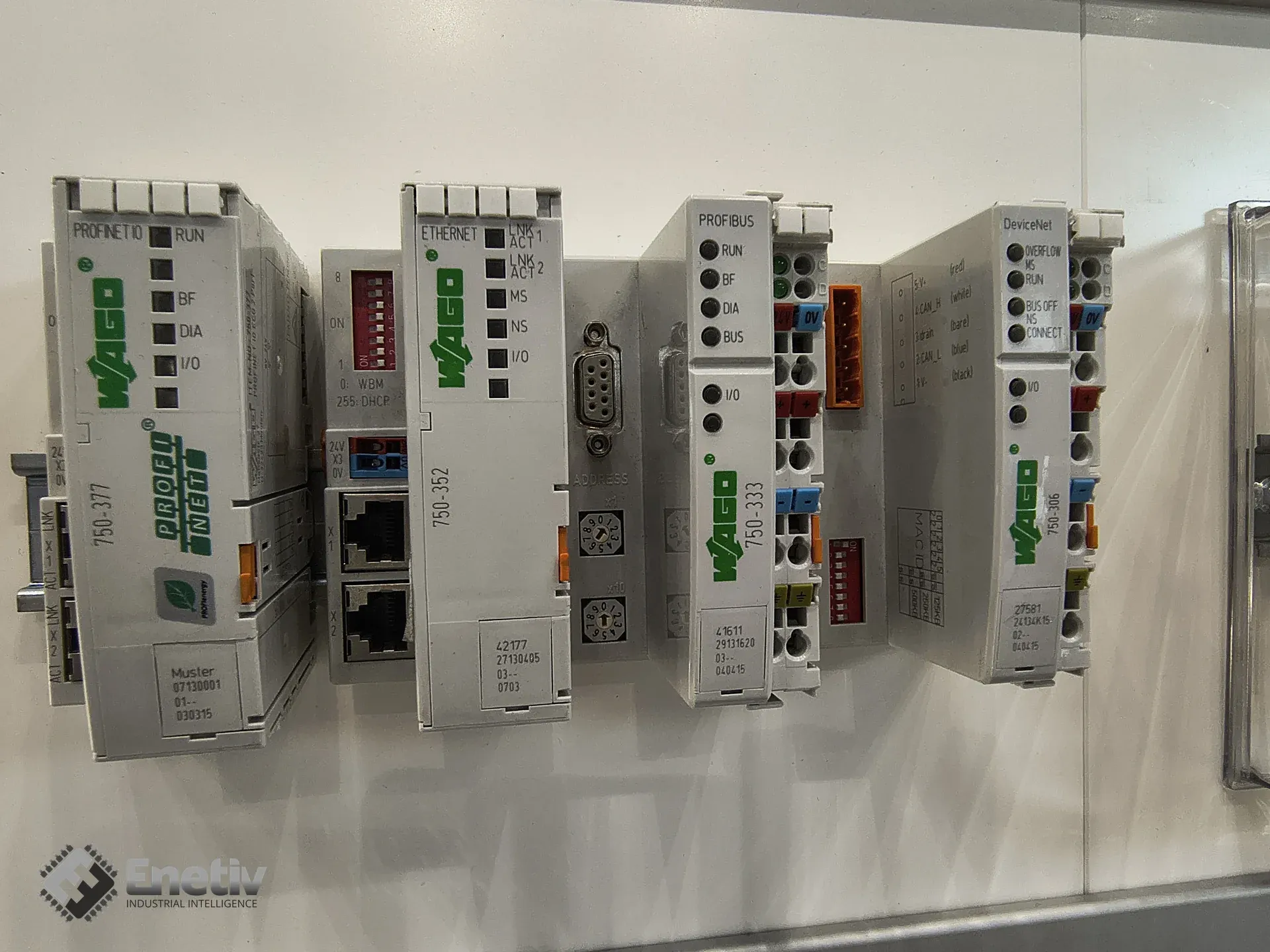
In short: 750-377 uses dual RJ-45 ports and the PROFINET IO protocol, 750-352 offers two RJ-45 ports with EtherNet/IP and Modbus TCP/UDP support, 750-333 communicates via a single-wire D-sub 9 socket on a PROFIBUS DP network, and 750-306 is designed for DeviceNet networks and uses a 5-pin male connector instead of D-sub.
750-377 – PROFINET IO module (dual RJ-45, DCP/DIP)
The 750-377 is a PROFINET IO fieldbus coupler with two RJ-45 ports and a built-in 100 Mbit/s switch enabling line topology. According to the manufacturer's datasheet, it supports up to 64 I/O modules in a single WAGO-I/O-SYSTEM 750 node. The device name can be set via the DCP protocol or traditional DIP switches (setting "8=OFF:DCP") – confirmed in WAGO documentation. Diagnostic LEDs on the related family of PROFINET couplers (2nd and 3rd generation) include RUN, BF, DIA, I/O, LNK and ACT, plus supply-voltage indicators A/B; exact labeling may vary slightly between hardware variants, so it's worth verifying against the manual for your specific unit. Power is supplied via two CAGE CLAMP® connectors, and device configuration is done through a 4-pin connector.
750-352 – Ethernet module (EtherNet/IP, Modbus TCP/UDP, dual RJ-45, DIP for IP)
The 750-352 is an Ethernet fieldbus coupler designed for EtherNet/IP and Modbus TCP/UDP communication. It has two RJ-45 ports and a built-in switch, enabling line topology in the WAGO 750 system. According to the verified manufacturer datasheet, the module is specified for operation on Cat. 5 twisted-pair cabling (max. cable length 100 m) – not Cat. 6A, as is sometimes incorrectly stated (Cat. 6A/T568A/AWG specifications apply to separate, optional WAGO plug connectors from the 750-977/978/979 series, not to the coupler module itself). The IP address can be set via a DIP switch – the last byte of the address and the mode (DHCP, BootP, static) are configurable. Diagnostic LEDs: LINK/ACT (green, port 1 / 2), MS (red/green, module status), NS (red/green, network status) and I/O (red/green/orange, local bus status) – all confirmed in WAGO documentation. Power is likewise supplied via two CAGE CLAMP® connectors.
750-333 – PROFIBUS DP module (D-sub 9, 12 MBd, LED diagnostics)
The 750-333 is a second-generation Fieldbus Coupler PROFIBUS DP, operating at 12 MBd (range 9.6 kBd–12 MBd) and connected via a single-wire D-sub 9 socket – confirmed in the manufacturer's datasheet. It maps the process data of all WAGO I/O modules onto the PROFIBUS DP/V1 bus. The verified manufacturer manual confirms the following diagnostic LEDs: RUN (green – coupler correctly initialized), BF (red – PROFIBUS communication status), DIA (red – external diagnostics present), BUS (red – configuration fault), I/O (red/green/orange – node status and error blink codes), and supply-voltage indicators A and C (green – presence of system voltage and field-side supply voltage).
750-306 – DeviceNet module (5-pin connector, EDS-file configuration)
The 750-306 is designed for DeviceNet networks. According to the verified, publicly available manufacturer datasheet (contrary to earlier assumptions of "no public data"), the module uses a 5-pin male connector for DeviceNet communication (not D-sub 9), plus an additional 4-pin connector for configuration. It supports three transmission speeds: 125 kBd, 250 kBd, and 500 kBd. Configuration is performed via EDS files (Electronic Data Sheet) in configuration software – the module is not addressed via DIP switches as is common on other fieldbus networks. A detailed list of diagnostic LEDs is not available in the publicly published datasheet – full details can be found in the dedicated product manual (DeviceNet Fieldbus Coupler, manual version V 2.0.0), which is worth downloading directly from the WAGO website before commissioning.
How to physically connect each communication head to the WAGO 750 system?
Key connection differences:
- 750-377 and 750-352: two RJ-45 ports with a built-in switch, enabling simple line topology. Power is supplied via two CAGE CLAMP® connectors.
- 750-333: a single D-sub 9 (9-pin) socket for the PROFIBUS DP bus, power likewise via CAGE CLAMP®.
- 750-306: a 5-pin male connector for the DeviceNet bus plus a separate 4-pin connector for configuration – confirmed in the manufacturer's datasheet.
How to configure addressing and network parameters on each module?
Addressing differs depending on the protocol:
- 750-377 (PROFINET): device name assigned via the DCP protocol or set manually via DIP switch (the "8=OFF:DCP" option).
- 750-352 (Ethernet): a DIP switch sets the last byte of the IP address and the assignment mode (DHCP, BootP, static). Configuration is done via WAGO-I/O-Check or WAGO-I/O-PRO software.
- 750-333 (PROFIBUS): addressing is handled through the module structure, auto-recognized by the coupler for the PROFIBUS process image; the node ID is typically set at the master/network configuration level rather than on the coupler itself.
- 750-306 (DeviceNet): configuration is done exclusively via EDS files loaded in configuration software – the module has no DIP switches for setting the node number or transmission speed.
How to interpret the diagnostic LEDs on each module?
LED diagnostics allow quick problem identification:
- 750-377: RUN – module correctly initialized; BF – PROFINET IO data exchange error; DIA – external diagnostics present; I/O – node status (colors/blink codes); ACT/LNK – Ethernet connection status (green = link, blinking = activity). Verify exact labeling against the manual for your hardware variant.
- 750-352: LINK/ACT – connection and transmission on RJ-45 ports; MS – module status (red = error, green = OK); NS – network status; I/O – local bus status.
- 750-333: RUN – coupler correctly initialized; BF – PROFIBUS communication error; DIA – external diagnostics present; BUS – configuration fault; I/O – node status; A/C – system and field supply voltage (red = absent, green = OK).
- 750-306: detailed LED list not available in the public datasheet – check the dedicated product manual (DeviceNet Fieldbus Coupler) before commissioning.
How to build a practical checklist when ordering a communication module replacement?
- Verify which protocol the existing network requires: PROFINET, EtherNet/IP, Modbus TCP, PROFIBUS DP, or DeviceNet.
- Check the full part number – don't order "WAGO 750," order the specific model (e.g. 750-377).
- Make sure the physical interface (RJ-45, D-sub 9, 5-pin DeviceNet connector) matches your existing cabling infrastructure – for the 750-352, verify the cabling meets at least Cat. 5.
- Confirm the addressing method:
- PROFINET – DCP or DIP.
- Ethernet – DIP setting the last IP byte and mode (DHCP/Static).
- PROFIBUS – module structure configuration on the master/coupler side.
- DeviceNet – EDS files only, no DIP switches.
- Check whether the node requires a line switch (Ethernet) and whether the existing CAGE CLAMP® power supply is compatible.
- Compare diagnostic LEDs – when replacing with a new module, make sure they behave the same as the original (verify in the manual if the hardware generation differs).
- Make sure all I/O modules (digital, analog) remain compatible – replacing just the head doesn't affect their functionality.
FAQ
How can I identify which communication module is installed in an existing WAGO 750 node?
Check the label on top of the module – the part number (e.g. 750-377) is clearly printed. Additionally, the connector type (RJ-45, D-sub, or 5-pin DeviceNet connector) and the presence of a DIP switch help confirm the protocol type.
Can I swap a 750-377 for a 750-352 without rewiring?
Yes, both modules use dual RJ-45 ports and a built-in switch, so they physically fit (provided the cabling meets at least Cat. 5). However, you'll need to change the network configuration (IP vs. DCP) and confirm your PLC supports the chosen protocol (EtherNet/IP or Modbus TCP/UDP).
What are common causes of a blinking BF LED on the 750-333?
The BF LED indicates a PROFIBUS communication error – common causes include an incorrect node address set at the master, damaged D-sub wiring, or a mismatched transmission speed (12 MBd vs. a different setting elsewhere).
Can I use one WAGO 750 node with different communication heads across an installation?
Yes, the I/O node is modular – you can swap only the communication head, as long as all other I/O modules remain compatible with the selected protocol and power supply.
What are the maintenance costs of each protocol in an industrial environment?
Costs depend on licensing requirements, availability of diagnostic tools, and network requirements. PROFINET and EtherNet/IP typically require more expensive industrial switches but offer higher throughput. PROFIBUS and DeviceNet are older, often cheaper to implement, but limited in speed and node count.
Where can I get full technical documentation for the 750-306 module?
The full datasheet is publicly available on the WAGO website and through authorized distributors (see Sources section). The complete diagnostic LED description is in the dedicated DeviceNet Fieldbus Coupler product manual (version V 2.0.0), available for download in the Downloads section of the manufacturer's website.
Summary and Contact
Choosing the right communication head in the WAGO-I/O-SYSTEM 750 eliminates the risk of incompatibility, speeds up diagnostics, and reduces maintenance costs. Remember: I/O modules are interchangeable, but it's the communication head (750-377 PROFINET, 750-352 Ethernet, 750-333 PROFIBUS DP, 750-306 DeviceNet) that defines the entire network architecture. If you work with industrial automation systems from manufacturers such as Allen-Bradley, Danfoss, ABB, and other industry leaders, correctly matching your WAGO 750 communication module is key to installation reliability.
Enetiv is a distributor of leading brands including WAGO, Allen-Bradley, Danfoss, and ABB, offering significant discounts for integrators and maintenance teams. For more information, technical advice, or a quote, contact us via the Enetiv contact page (enetiv.com/kontakt).
Sources
- WAGO – Fieldbus Coupler PROFINET IO (750-377), product page and datasheet (dual RJ-45, 100 Mbit/s switch, max. 64 modules, DCP/DIP): https://www.wago.com/global/i-o-systems/fieldbus-coupler-profinet-io/p/750-377 and https://pim.galco.com/Manufacturer/Wago/TechDocument/Data%20Sheet/750-377_dat.pdf
- WAGO – Fieldbus Coupler ETHERNET (750-352), datasheet (dual RJ-45, Cat. 5, EtherNet/IP, Modbus TCP/UDP, LINK/ACT/MS/NS/I-O LEDs): https://pim.galco.com/Manufacturer/Wago/TechDocument/Data%20Sheet/750-352_dat.pdf
- WAGO – Fieldbus Coupler PROFIBUS DP (750-333), datasheet and manual (D-sub 9, 12 MBd, RUN/BF/DIA/BUS/I-O/A/C LEDs): https://s3.amazonaws.com/shopforautomation.com/WAGO_DATASHEET/750-333.pdf and https://asset.conrad.com/media10/add/160267/c1/-/en/000197014ML02/manual-197014-wago-fc-profibus-g2-12mbd-plc-fieldbus-connector-750-333-1-pcs.pdf
- WAGO – Fieldbus Coupler DeviceNet (750-306), product page and datasheet (5-pin connector, EDS configuration, 125/250/500 kBd speeds): https://www.wago.com/global/i-o-systems/fieldbus-coupler-devicenet/p/750-306 and https://www.farnell.com/datasheets/3963635.pdf
- WAGO – WAGO-I/O-SYSTEM 750 Manual, general diagnostic LED documentation for the PROFINET coupler family (750-375 as a related generation): https://www.manualslib.com/manual/1903182/Wago-Wago-I-O-System-750.html